Gasket is one of the basic elements for flanged joints in piping system of process plants. A gasket can be defined as a material or combination of materials clamped between two separable mechanical members of a mechanical joint (flanged joint) which produces the weakest link of the joint. Gaskets are used to create a static seal between two stationary members of a mechanical assembly (the flanged joint). The gasket material flows (interpose a semi-plastic material between the flange facings) into the imperfections between the mating surfaces by an external force (bolt tightening force) and maintain a tight seal (seals the minute surface irregularities to prevent leakage of the fluid) under operating conditions. The amount of flow (seal) of the gasket material that is required to produce a tight seal is dependent upon the roughness of the surface. The gasket must be able to maintain this seal under all the operating conditions of the system including extreme upsets of temperature and pressure. Therefore, it is important to ensure proper design and selection of the gaskets to prevent flange-leakage problems and avoid costly shutdowns of the process plants. The following article will try to explain the main points related to gaskets.


Working philosophy of a gasket to prevent leakage:
Refer the above figure which shows the three major forces acting on the gasket. Normally the gasket is seated by tightening the bolts on the flanges before the application of the internal pressure. Upon the application of the internal pressure in the joint, an end force (Hydrostatic end force) tends to separate the flanges and to decrease the unit stress (Residual stress) on the gasket. Leakage will occur under pressure if the hydrostatic end force is sufficiently great and the difference between hydrostatic end force and the bolt-load reduces the gasket load below a critical value. To explain it in more clear language we can say that there are three principal forces acting on any gasketed joint. They are:
- Bolt Load which applies the initial compressive load that flows the gasket material into surface imperfections to form a seal.
- The hydrostatic end force, that tends to separate flanges when the system is pressurized.
- Internal pressure acting on the portion of the gasket exposed to internal pressure, tending to blow the gasket out of the joint and/or to bypass the gasket under operating conditions.
Even though there are other shock forces that may be created due to sudden changes in temperature and pressure. Creep relaxation is another factor that may come into the picture. The initial compression force applied to a joint must serve several purposes.
- It must be sufficient to initially seat the gasket and flow the gasket into the imperfections on the gasket seating surfaces regardless of operating conditions.
- Initial compression force must be great enough to compensate for the total hydrostatic end force that would be present during operating conditions.
- It must be sufficient to maintain a residual load on the gasket/flange interface.
Now from a practical standpoint, residual load on the gasket must be “X” times internal pressure if a tight joint is required to be maintained. This unknown quantity “X” is what is specified as the “m” factor in the ASME Pressure Vessel Code and will vary depending upon the type of gasket being used. Actually the “m” value is the ratio of residual unit stress (bolt load minus hydrostatic end force) on gasket to internal pressure of the system. The larger the value of “m”, the more assurance the designer has of obtaining a tight joint.
Gasket Types:
Gaskets can be grouped into three main categories as follows:
- Non-metallic Gaskets: Usually composite sheet materials are used with flat face flanges and low pressure class applications. Non-metallic gaskets are manufactured non-asbestos material or Compressed Asbestos Fibre (CAF). Non-asbestos types include arimid fibre, glass fibre, elastomer, Teflon (PTFE) and flexible graphite gaskets. Full face gasket types are suitable for use with flat-face (FF) flanges and flat-ring gasket types are suitable for use with raised face (RF) flanges.
- Semi-metallic Gaskets: Semi-metallic gaskets are composites of metal and non-metallic materials. The metal is intended to offer the strength and resiliency while the non-metallic portion of a gasket provides conformability and sealability. Commonly used semi-metallic gaskets are spiral wound, metal jacketed, Cam profile and a variety of metal-reinforced graphite gaskets. Semi metallic gaskets are designed for the widest range of operating conditions of temperature and pressure. Semi-metallic gaskets are used on raised face, male-and female and tongue and groove flanges.
- Metallic Gaskets: Metallic gaskets are fabricated from one or a combination of metal to the desired shape and size. Common metallic gaskets are ring-joint gaskets and lens rings. They are suitable for high-pressure and temperature applications and require high bolt load to seal.
Common gasket configurations:
Aside from the choice of gasket material, the structure or configuration of the gasket is also significant. Following are descriptions of four major types.
- Graphite foil: The physical and chemical properties of graphite foil make it suitable as a sealing material for relatively arduous operating condition. In an oxidizing environment, graphite foil can be used in the temperature range of –200 to +500°C, and in a reducing atmosphere, it can be used at temperatures between –200 and 2,000°C. Because graphite foil has no binder materials, it has excellent chemical resistance, and is not affected by most of the commercially used common chemicals. It also has very good stress-relaxation properties.
- Spiral-wound: As the name implies, the spiral-wound gasket is made by winding a preformed-metal strip and a filler on the periphery of a metal winding mandrel. All spiral-wound gaskets are furnished with a centering ring. In addition to controlling compression, these rings serve to locate the gasket centrally within the bolt circle. Inner rings are used where the material (such as a gasket with PTFE filler) has a tendency for inward buckling. The ring also prevents the buildup of solids between the inside diameter of the gasket and the bore of pipe. Under vacuum condition, the ring protects against damage that would occur if a pieces of a broken component were drawn into the the system. Spiral-wound gaskets can operate at temperatures from –250 to 1,000°C, and pressures from vacuum to 350 bar. Spiral-wound gaskets up to 1-in. diameter and up to class number 600 require a uniform bolt stress of 25,000 psi to compress the gasket. Larger sizes and classes require 30,000 psi to compress the gasket.
- Ring-joint: Ring-joint gaskets are commonly used in grooved flanges for high-pressure-piping systems and vessels. Their applicable pressure range is from 1,000 to 15,000 psi. These gaskets are designed to give very high gasket pressure with moderate bolt load. These joints are not generally pressure-actuated. The hardness must be less than that of the flange material so that proper flow of material occurs without damaging flange surfaces. The most widely used ring-joint gaskets are of the oval and octagonal type. Oval-type gaskets contact the flange face at the curved surface and provide a highly reliable seal. However, the curved shape makes it more difficult to achieve accurate dimensioning and surface finishing. Oval gaskets also have the disadvantage that they can only be used once, so they may not be the best choice for sealing flanges that have to be opened routinely. On the other hand, because they are constructed of only straight faces, octagonal-type gaskets are usually less expensive, they can be dimensioned more accurately, and are easier to surface finish than the oval-type gasket. However, a greater torque load is required to flow the gasket material into imperfections that may reside on the flange faces. Octagonal gaskets can be used more than once.
- Corrugated-metal: This type of gasket is available in a wide range of metals, including brass, copper, coppernickel alloys, steel, monel, and aluminium. Corrugated metal gaskets can be manufactured to just about any shape and size required. The thickness of the metal is normally 0.25 or 0.3 mm, with corrugations having a pitch of 1.6, 3.2, and 6.4 mm. The sealing mechanism is based on point contact between the peaks of the corrugations and the mating flanges
Gasket Standards:
Following standards are normally adopted for specifying gaskets.
- ASME B16.21 Non-metallic flat gaskets for pipe flanges.
- ASME B16.20 Metallic Gaskets for steel pipe flanges, Ring Joint, Spiral Wound and Jacketed
- IS2712 Specification for compressed Asbestos fibre jointing.
- BS 3381 Sprial Wound Gaskets to suit BS 1560 Flanges
Selection of Gaskets:
- The gasket material selected should be one which is not adversely affected physically or chemically by the service conditions.
- The two types of gaskets most commonly known are ring gaskets and full face gaskets. The latter as the name implies, covers the entire flange face and are pierced by the bolt holes. They are intended for use with flat face flanges. Ring gaskets extend to the inside of the flange bolt holes and consequently are self centering. They are usually used with raised face or lap joint flanges but may also be used with flat-faced flanges.
- Flat-ring gaskets are widely used wherever service condition permits because of the ease with which they may be cut from flat sheet and installed. They are commonly fabricated from such materials as rubber, paper, cloth, asbestos, plastics, copper, lead, aluminum, nickel, monel, and soft iron. The gaskets are usually made in thickness from 1/64 to 1/8 in. Paper, cloth and rubber gaskets are not recommended for use above 120° C. Asbestos-composition gaskets may be used up to 350° C or slightly higher, ferrous and nickel-alloy metal gaskets may be used up to the maximum temperature rating of the flanges.
- Upon initial compression a gasket will flow both axially and radially. The axial flow is required to fill depressions in the flange facing and prevent leakage. Radial flow serves no useful purpose unless the gasket is confined. Where a flange joint is heated, a greater gasket pressure is produced due to the difference between the flange body and the bolts. This greater pressure coupled with the usual softening of the gasket material at elevated temperatures causes additional axial and radial gasket flow. To compensate for this, the flange bolts are usually re-tightened a second or third time after the joint is heated to the normal operating temperature. A thick gasket will flow radially to a far greater extent than a thin gasket. Some thin gaskets show practically no radial flow at extremely high unit pressures. Consequently, for high temperatures a thin gasket has the advantage of maintaining a permanent thickness while a thick gasket will continue to flow radially and may leak, in time, due to the resulting reduced gasket pressure. However in attempting utmost utilization of thin gasket advantage, one may find that gasket selected has insufficient thickness to seal the irregularities, in the commercial flange faces. The spiral wound asbestos-metallic gasket combines the advantages of both the thick and thin gasket. Although a relatively thick gasket (most common types are 0.175” thick) its spirally laminated construction confines the asbestos filler between axially flexible metal layers. This eliminates the radial flow characteristics of a thick gasket and provides the resiliency to adjust to vary service conditions. Spiral wound gaskets are available with different filler materials such as Teflon, grafoil etc. to suit fluid compatibility. Spiral wound gaskets used with raised face flanges usually have an inner metal ring and an outer centering ring.
- Laminated gaskets are fabricated with a metal jacket and a soft filler, usually of asbestos. Such gaskets can be used up to temperatures of about 400° C to 450° C and require less bolt load to seat and keep tight than solid metal flat ring gaskets.
- Serrated metal gaskets are fabricated of solid metal and have concentric grooves machined into the faces. This greatly reduces the contact area on initially tightening thereby reducing the bolt load. As the gasket is deformed, the contact surface area increases. Serrated gaskets are useful where soft gaskets or laminated gaskets are unsatisfactory and bolt load is excessive with a flat-ring metal gasket. Smooth-finished flange faces should be used with serrated gaskets.
- Corrugated gaskets with asbestos filling are similar to laminated gaskets except that the surface is rigid with concentric rings as with the case of serrated gaskets. Corrugated gaskets require less seating force than laminated or serrated gaskets and are extensively used in low-pressure liquid and gas service. Corrugated metal gaskets without asbestos may be used to higher temperature than those with asbestos filling.
- Two standard types of ring-joint gaskets are available for high-pressure service. One type has an oval cross section, and the other has an octagonal cross section. These rings are fabricated of solid metal, usually soft iron, soft steel, monel, 4-6% chrome, and stainless steels. The alloy-steel rings should be heat treated to soften them.
- It is recommended that ring joint gasket be used for class 150 flanged joints. When the ring joint or spiral wound gasket is selected, it is recommended that line flanges be of the welding neck type.
Parameters affecting Gasket performance:
The performance of the gasket is affected by a number of factors. All of these factors must be taken into consideration when selecting a gasket:
- The Flange Load: All gasket materials must have sufficient flange pressure to compress the gasket enough to insure that a tight, unbroken seal occurs. The flange pressure, or minimum seating stress, necessary to accomplish this is known as the “y” factor. This flange pressure must be applied uniformly across the entire seating area to achieve perfect sealing. However, in actual service, the distribution around the gasket is not uniform. The greatest force is exerted on the area directly surrounding the bolts. The lowest force occurs mid-way between two bolts. This factor must be taken into account by the flange designer.
- The Internal Pressure: In service, as soon as pressure is applied to the vessel, the initial gasket compression is reduced by the internal pressure acting against the gasket (blowout pressure) and the flanges (hydrostatic end force). To account for this, an additional preload must be placed on the gasket material. An “m” or maintenance factor has been established by ASME to account for this preload. The “m” factor defines how many times the residual load (original load minus the internal pressure) must exceed the internal pressure. In this calculation, the normal pressure and the test pressure should be taken into account.
- Temperature: The effects of both ambient and process temperature on the gasket material, the flanges and the bolts must be taken into account. These effects include bolt elongation, creep relaxation of the gasket material or thermal degradation. This can result in a reduction of the flange load. The higher he operating temperature, the more care needs to be taken with the asket material selection. As the system is pressurized and heated, the joint deforms. Different coefficients of expansion between the bolts, the flanges and the pipe can result in forces which can affect the gasket. The relative stiffness of the bolted joint determines whether there is a net gain or loss in the bolt load. Generally, flexible joints lose bolt load.
- Fluid: The media being sealed, usually a liquid or a gas with a gas being harder to seal than a liquid. The effect of temperature on many fluids causes them to become more aggressive. Therefore, a fluid that can be sealed at ambient temperature, may adversely affect the gasket at a higher temperature. The gasket material must be resistant to corrosive attack from the fluid. It should chemically resist the system fluid to prevent serious impairment of its physical properties.
- Surface Finish of the Gasket: The surface finish of a gasket — which consists of grooves or channels pressed or machined onto the outer surface — governs the thickness and compressibility required by the gasket material to form a physical barrier in the clearance gap between the flanges. A finish that is too fine or shallow is undesirable, especially on hard gasket materials, because the smooth surface may lack the required grip, which will allow extrusion to occur. On the other hand, a finish that is too deep will yield a gasket that requires a higher bolt load, which may make it difficult to form a tight seal, especially when large flange surfaces are involved. Fine machining marks applied to the flange face, tangent to the direction of applied fluid pressure can also be helpful. Flange faces with non-slip grooves that are approximately 0.125 mm deep are recommended for gaskets more than 0.5 mm thick; and for thinner gaskets, grooves 0.065 mm deep are recommended. Under no circumstances should the flange-sealing surface be machined with tool marks extending radially across the gasket-sealing surface; such marks could allow leakage.
- Gasket Thickness: For a given material, it is a general rule that a thinner gasket is able to handle a higher compressive stresses than thicker one. However, thinner materials require a higher surface finish quality. As a rule of thumb, the gasket should be at least four times thicker than the maximum surface roughness of the flange faces. The gasket must be thick enough to occupy the shape of the flange faces and still compress under the bolt load. In situations where vibration is unavoidable, a thicker gasket than the minimum required should be employed.
- Gasket Width: In order to reduce the bolt load required to produce a particular gasket pressure, it is advisable not to have the gasket wider than is necessary. For a given gasket stress, a raised face flange with a narrow gasket will require less pre-load, and thus less flange strength than a full-face gasket. In general, high-pressure gaskets tend to be narrow.
- Stress Relaxation: This factor is a measure of the material’s resiliency over a period of time, and is normally expressed as a percentage loss per unit of time. All gasket material will lose some resiliency over time, due to the flow or thinning of the material caused by the applied pressure. After some initial relaxation, the residual stress should remain constant for the gasket.
- Gasket Outer Diameter: For two gaskets made of the same material and having the same width, the one with a larger outer diameter will withstand a higher pressure. Therefore, it is advisable to use a gasket with an external diameter that is as large as possible.
Provide your input in comments section
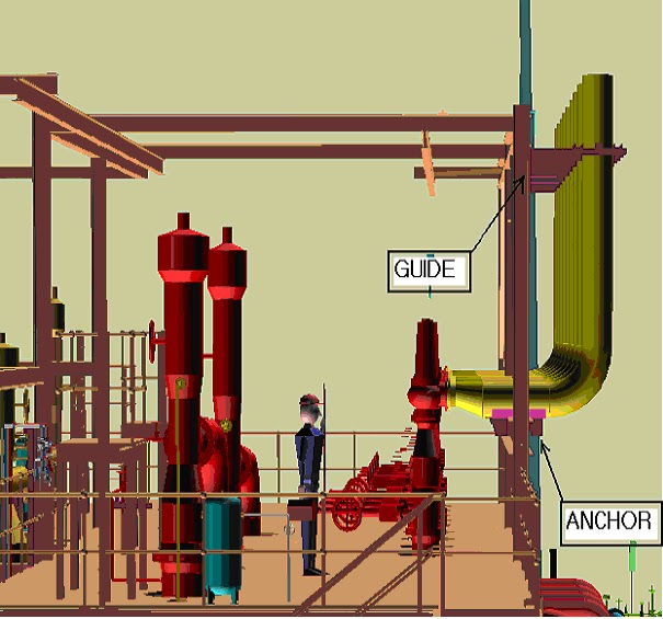


I feel the sign convention matches with that of CAESAR II convention. the direction of PSV outlet piping determines the direction (sign) of the force acting on the first elbow. It will be in the direction from PSV outlet towards first elbow, with CII sign convention (positive or negative)
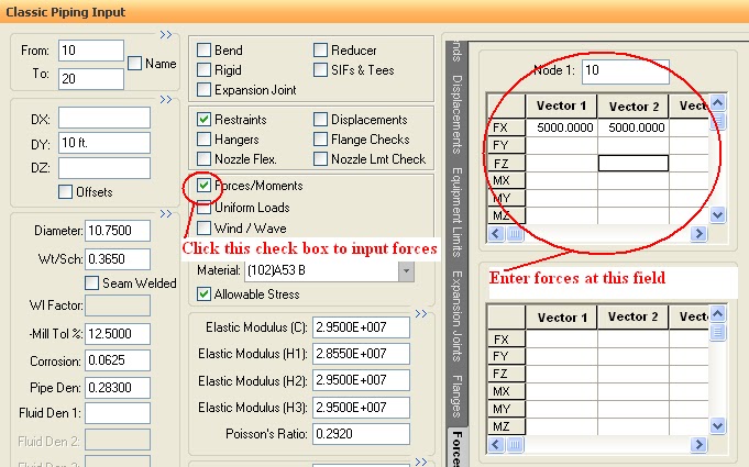
I feel that entering force values in Vector 1 and Vector 2 at the same node is not correct. It has been done only for explanation, I feel by Mr. Dey. Vector 1 corresponds to F1 and should be entered for PSV-1 pop up case at elbow-1 node.
Vector 2 corresponds to F2 and should be entered for PSV-2 pop up case at elbow-2 node.
Hope this helps. Thanks.
I feel the sign convention matches with that of CAESAR II convention. the direction of PSV outlet piping determines the direction (sign) of the force acting on the first elbow. It will be in the direction from PSV outlet towards first elbow, with CII sign convention (positive or negative)
I feel that entering force values in Vector 1 and Vector 2 at the same node is not correct. It has been done only for explanation, I feel by Mr. Dey. Vector 1 corresponds to F1 and should be entered for PSV-1 pop up case at elbow-1 node.
Vector 2 corresponds to F2 and should be entered for PSV-2 pop up case at elbow-2 node.
Hope this helps. Thanks.
if we use proper guides to the inlet piping of psv why cant we provide the springs on the inlet piping. Sometimes in the temperature range of more than 330 deg cel resting support will not work in hot sustained case so we need to provide the springs. We cant use the loops as of limitations of the pressure drop.
In open system, also input reaction force at first bend to reached last point that open to atmospheric or not ?.
In close system, also input reaction force at next bend to reached header or not ?
would you please explain what is diffrence between “RV. POP CONDITION” AND “ESTABLISHED FLOW CONDITION” ?
also what is diffrence between load cases for these two condition?
Thank you for good text. I have wondering the open type SRV with vent pipe. Nonmandatory appendix of ASME B31.1 shows the calculation of the force in the vent pipe. The same rule could be applied to the vent pipe or any further consideration is required?